

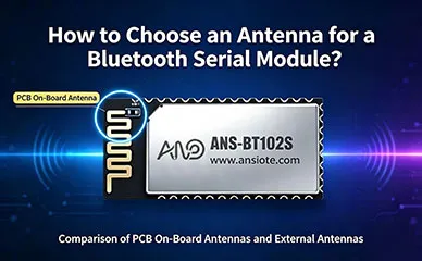
In the development of IoT devices, the selection of Bluetooth serial modules often focuses on the chipset, energiförbrukning, or data throughput, while the antenna—the “RF gateway”—is frequently relegated to an afterthought. It is often not until the final product validation stage—when transmission range falls short or signals are blocked by a metal enclosure—that engineers revisit their antenna choice, by which point there is rarely room for significant design changes.
As a wireless module manufacturer based in Shenzhen, Ansiot Technology has gained extensive, hands-on experience in antenna selection while serving clients in industrial data transmission, medical equipment, and smart home sectors. Drawing on the design of the Ansiot ANS-BT102S Bluetooth module, this article explores the logic behind selecting an antenna for Bluetooth serial modules: the ideal use cases for onboard versus external antennas, how to properly allocate “clearance zones,” and the process for implementing custom external antennas.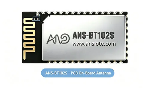
Why the Antenna Is an Underestimated Factor in Bluetooth Module Selection
The antenna determines the performance of the RF signal over the “last meter.” Regardless of how superior the chipset is or how high the transmit power may be, poor antenna matching or restrictive layout will severely compromise both communication range and stability. Common issues include:
Metal enclosure shielding: 2.4GHz signals can barely penetrate metal; if a device is housed in a metal casing, an onboard antenna becomes effectively useless.
Encroachment on clearance zones: In densely packed PCB layouts, the antenna area may be compromised by traces, copper pours, or tall components, leading to a shift in the resonant frequency.
Proximity to interference sources: Placing components like switching power supplies, motor drivers, or display ribbon cables too close to the antenna significantly degrades the signal-to-noise ratio (SNR).
Spending just ten minutes evaluating these factors during the selection phase can prevent costly product rework later on. Nedan, we break down the two primary antenna solutions.
PCB Onboard Antennas: Balancing Integration and Consistency
Ansiot Technology’s current flagship BLE 5.2 serial modules (such as the ANS-BT102S) feature an integrated PCB onboard antenna by default. This choice is not a compromise made for the sake of cost, but rather one based on careful consideration of the actual application scenarios encountered by a wide range of customers.
Three Key Advantages of Onboard Antennas
High Integration: The antenna is etched directly onto the module’s PCB, eliminating the need for customers to source additional antenna components or perform extra assembly steps during final product manufacturing.
Excellent Consistency: Issues such as loose antenna connectors, poor contact at IPEX sockets, or assembly tolerances are avoided, ensuring stable RF performance across mass-produced batches.
Lower Total Cost: By eliminating the need for external antennas, feed cables, and associated assembly labor, this solution is particularly advantageous for cost-sensitive projects.
For devices such as barcode scanners, industrial sensors, and medical/healthcare equipment, the module can simply be mounted onto the mainboard, allowing for seamless integration without disrupting production throughput.
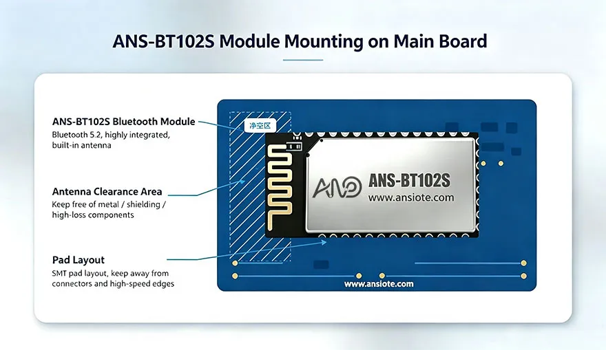
Prerequisite: De “Keep-Out Zone” Requirement
Onboard antennas also have clear limitations—they are susceptible to interference from the mainboard, and achieving a perfectly omnidirectional radiation pattern can be challenging. Technical documentation consistently emphasizes the following:
A strict “keep-out zone” must be maintained beneath and around the module’s antenna area; no PCB traces, copper pours, or components exceeding a specified height are permitted.
Large metal structures—such as batteries, shielding cans, or metal brackets—must not be placed within the projection area of the antenna.
If the device contains high-power switching power supplies or motor drives, the potential impact on the onboard antenna’s performance must be carefully evaluated.
Consequently, onboard antenna solutions are best suited for compact devices with plastic enclosures operating in relatively “clean” RF environments—a typical scenario for most indoor consumer electronics and light industrial equipment.
External Antenna Solutions: The Price of Enhanced Performance is “Anpassning”
When Should You Consider an External Antenna?
An onboard antenna is often insufficient if your project encounters any of the following situations:
The device features a metal enclosure that prevents the antenna from “extending” outside the casing.
The antenna must be positioned behind a battery or display, making it impossible to maintain the required keep-out zone.
The application requires a longer transmission range or specific directional characteristics (till exempel, point-to-point directional communication).
Why Do Ansiot’s External Antennas Require Custom Impedance Matching?
It is important to note that external antennas are not “plug-and-play” off-the-shelf components. Unlike some modules on the market that feature IPEX connectors, our Bluetooth modules typically expose their RF pins via “stamp holes” (castellated holes). Consequently, an external antenna must be connected to the module’s RF port through a matching circuit, which is then fine-tuned based on the specific PCB layout and the material of the device enclosure.
The process involves our technical team working directly with the client during the PCBA design phase. We assist in adjusting the parameters of a π-network matching circuit—typically by fine-tuning a combination of 0402-sized capacitors and inductors. When necessary, we use a network analyzer to measure the Standing Wave Ratio (SWR), ensuring that the antenna’s efficiency and directivity meet the required specifications. Clients should account for a dedicated tuning phase in their development schedule and provide the PCBA or device enclosure samples for our RF engineers to conduct these measurements.
While this customization process requires an additional upfront R&D investment, it ensures predictable and controllable RF performance. External antennas can be positioned away from interference sources on the mainboard, and their directivity can be optimized based on the intended orientation of the end product. For applications such as industrial data transmission, long-range telemetry and monitoring, or devices housed in metal enclosures, this investment is well worth it.
On-board Antennas vs. External Antennas: A Comparison Guide
| Comparison Dimension | PCB-Integrated Antenna | External Antenna (Custom) |
| 集Integration Cost | Lowest; no additional components required | Higher; includes antenna, matching components, and tuning/debugging |
| Consistency | High; no assembly-related variables | Depends on the precision of impedance matching and tuning |
| Metal Enclosure Compatibility | ✗ Not compatible | ✓ Compatible |
| Transmission Range | Short to medium range (tens of meters) | Can be significantly extended |
| Design Cycle | Ready-to-use (plug-and-play) | Requires time for impedance matching and tuning |
| Typiska applikationer | Barcode scanners, sensorer, medical equipment | Industrial data transmission, metal-encased equipment, long-range monitoring |
A Four-Step Selection Strategy for Engineers
Among the clients we serve, there have been several instances where overlooking antenna selection during the design phase led to costly rework later in the project. We recommend that engineers follow this decision-making sequence:
Första, determine the enclosure material and structure: If the enclosure is plastic and a clear space (keep-out zone) can be maintained for the antenna, prioritize an on-board antenna solution. If the enclosure is metal, proceed directly to evaluating an external antenna solution.
Verify keep-out requirements: Refer to the antenna zone dimensions specified in the module’s datasheet and reserve a corresponding keep-out area on the device’s PCB—ensuring no traces or copper pours are placed within this zone.
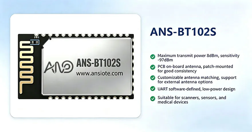
Evaluate communication range requirements: The ANS-BT102S features a maximum transmit power of 8 dBm and a sensitivity of -97 dBm; with an optimized layout, it can support most short-range, transparent data transmission scenarios—both indoors and outdoors. If specific, long-range performance requirements exist, consider a custom external antenna solution.
Allocate time for tuning and debugging: When opting for an external antenna, provide the device’s PCBA or enclosure samples in advance, and coordinate with the Ansiot RF team to schedule antenna matching and tuning.
There is no such thing as an inherently “better” eller “worse” antenna—only one that is well-matched or poorly matched to its environment. By defaulting to an on-board PCB antenna while offering custom external antenna options, we enable most clients to achieve reliable Bluetooth connectivity at the lowest possible integration cost, while also providing a pathway for performance upgrades in specialized use cases.